Modeling in Cameo for the Xcelerator Digital Thread
An onboarding guide for Lockheed systems engineers and electrical architects: what to model in Cameo, and how, so your work flows automatically downstream into Teamcenter and Capital.
1Onboarding & Overview
1.1 What this guide is, and isn't
This is a modeling guide. It tells you what to build in Cameo and why. It is not a Cameo training manual (it won't teach you the software's menus from scratch), and it is not a tool administrator's guide (it won't tell you how to configure the connector between systems).
It exists because there is a real gap between how Lockheed has been modeling for the last ten years and how this guide asks you to model going forward. That gap matters enough that we explain it directly, in Section 1.4, instead of glossing over it.
Every technical claim in this guide comes from real working sessions between the Lockheed and Siemens teams building this connection, not from a manual or a guess. Where something is still unresolved, we say so plainly instead of pretending it's settled.
1.2 The big picture: three tools, one thread
Three systems work together to take a design from an idea to a finished electrical architecture.
Cameo is where a systems engineer designs the system: what it's made of, and what it does. This is where your work starts.
Teamcenter is the backbone. It stores the design, connects it to everything else in the program (requirements, other disciplines, change records), and acts as the single source of truth.
Capital is where the electrical architecture, the actual wiring, signals, and components, gets designed, based on what came from Cameo through Teamcenter.
A tool called the HCL Cameo-Teamcenter connector sits between Cameo and Teamcenter and does the actual moving of data. You don't operate it directly very often; mostly you'll see two buttons: Mark for Deep Sync and Put Model. When you mark something and put it, the connector reads your Cameo model and pushes what it finds into Teamcenter, following rules set up by your PLM administrator.
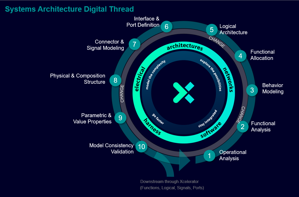
Within Cameo itself, that modeling work follows its own sequence, ten steps that build on each other from operational intent down to a model that's ready to validate.
1.3 A few words you'll see everywhere
Full definitions live in the Glossary, but here are the load-bearing ones up front.
- Model: the Cameo file you're building. It represents your understanding of the system.
- Function: something the system does. In Cameo, you model this as an Activity.
- Logical block: something the system is made of. In Cameo, you model this as a Block.
- Port: a connection point on a block, where something goes in or out.
- Allocation: the link that says "this function is performed by this block."
- Digital thread: the connected, traceable path of information from Cameo, through Teamcenter, into Capital, and back.
1.4 Where Lockheed stands today, and why this guide exists
Here is the honest picture, worth reading carefully, because it explains the whole reason this guide exists.
For roughly the last ten years, on both the Wildfire program and the Quick Start Data (QSD) program, Lockheed's Cameo-to-Capital connection has worked by feeding only one kind of information downstream: part properties, the structure of the system, the "bag of parts and ports" you build in an Internal Block Diagram. It has never fed Activities, the behavior, the functions the system performs, into Capital at all.
Siemens has been working to change this for more than five years. This guide is that change. It is not a description of how things have always been done. It is a new, more complete standard: one where both structure (what the system is made of) and behavior (what the system does) cross the bridge, consistently, instead of only structure.
Lockheed does have its own internal modeling methodology, nicknamed M³ (also called MBSC), documented on an internal Confluence site. But by its own documentation, it is not mandatory. Programs are explicitly told to fall back to their own tailoring guidance when M³ doesn't fit. The result is that practice currently varies significantly from program to program. This guide's job is to give every program the same, defensible answer to "how do I model this so it survives the trip downstream," instead of leaving each one to improvise.
If you've been modeling with part properties only for years, you are not doing anything wrong; you were following the only path that existed. This guide adds the missing half.
1.5 Who does what
| Role | Responsible for |
|---|---|
| Systems Engineer | Modeling functions (Activities), structure (Blocks, Parts, Ports), and the links between them, in Cameo |
| PLM Administrator | Owning the HCL connector configuration and the Teamcenter mapping file: the rules that decide what crosses and how |
| Electrical Architect | Working in Capital with the structure and function data that arrives from Teamcenter |
| Program / Configuration Management | Making sure the whole chain, function to logical block to electrical component, stays traceable |
1.6 Quick starts by role
A condensed "day one" for each role. Each one names what to check before you start, then points at the sections that matter most for that role, so you don't have to read the whole guide before doing anything.
Systems Engineer
Before you start: confirm Cameo has the SysML profile enabled and you have access to your program's shared Interface Block library. If you're not sure, ask your PLM administrator.
- Read Section 3 in full, especially 3.4, the one genuinely hard part.
- Do the Worked Example once before touching a real model.
- Run the 3.5 checklist against your own model before every Mark for Deep Sync.
- Try the practice exercise in Section 4 to check the checklist actually sticks.
PLM Administrator
Before you start: you own the Teamcenter mapping file and the HCL connector configuration; nothing in Section 3 works without these being set up first.
- Read 3.2 to know exactly what a modeler expects to see land, and where tagged values need explicit mapping entries.
- Read Section 5 in full, it's written from your side of the fence.
Electrical Architect
Before you start: you're the receiving end of this thread. You don't need to model in Cameo, but you do need to recognize what a correctly-modeled Function, Signal, and Component should look like when they arrive.
- Read the 3.2 element map and the diagram beneath it, that's your side of the table.
- Section 5.3 tells you what should already be there versus what still needs manual entry on your side.
Program / Configuration Management
Before you start: this guide represents a change in modeling practice, not just a tool tip. Section 1.4 is worth reading in full before anything else.
- Read Section 2 for the traceability and change-cycle case.
2Value to Lockheed: Reducing Design and Change Cycles
2.1 The problem today, stated plainly
There are two real, specific problems, not hypothetical ones.
First: behavior has had no path downstream at all. Everything about what the system does, every Activity diagram, every function, has lived in Cameo and stayed there. Only structure made it into Capital. If an electrical architect needed to understand what a component was for, that understanding lived in someone's head or in a document, not in the connected model.
Second: even where data does cross today, it's easy to make it look connected without it actually being meaningful. During one of the working sessions behind this guide, an early AI-assisted attempt to link a function to the block that performs it used a plain Allocate relationship. It is a valid SysML element, but not semantically rich enough on its own: it doesn't carry the data and control distinction a real function-to-structure link needs (see 3.4). A model can look wired together in Cameo and still fail to carry real meaning once it crosses into Teamcenter and Capital. Section 3 shows how to avoid that trap.
2.2 What correct modeling actually buys you
It catches broken designs before they become invisible. Capital already has a rule that every signal needs at least one input and at least one output: if a function only has outputs connected, or only inputs, Capital flags it as an error. Cameo has a matching kind of check: if a port's declared flow direction disagrees with how you've drawn an item flow using it, Cameo will tell you. Without these checks, a missing connection produces no data and no error, the function simply does nothing, with no indication of why. Modeling correctly turns a silent, invisible gap into an error you catch on your screen, in Cameo, instead of a mystery an electrical architect discovers weeks later.
Behavior finally gets a path to Capital. Once your Activities are modeled the way Section 3 describes, the functions you already design in Cameo become real Capital functions automatically; nobody has to re-enter them by hand on the Capital side.
One standard, not eleven programs each guessing. Because Lockheed's own methodology isn't mandatory, the single biggest value this guide offers is consistency: every program gets the same answer to "how do I model this correctly," instead of each one inventing its own convention and discovering the differences the hard way during an integration.
Where this shows up across the design cycle. The earlier a function or a connection is modeled correctly, the earlier a broken design gets caught, during architecture work, not during detailed design, and never after the fact during a costly change. That's the whole logic behind reducing design and change cycle time: catch it in Cameo, where it's cheap to fix, not downstream, where it isn't.
2.3 Honest caveats
This connection is real and working, but it is not a finished, closed system, and it does not replace engineering judgment. As of the working sessions behind this guide, two things were still genuinely open:
- There is no Teamcenter object today that can hold a function's full pin/signature information (its inputs and its return value). Extending Teamcenter's data model to add one is being actively weighed against other priorities; it is not yet decided.
- Whether Cameo's flow-direction validation check works reliably for both of the two valid modeling styles described in Section 3.3 was not yet confirmed.
Since that first round of sessions, the connector was driven headlessly through 21 real Check-Ins on a live Teamcenter, with every claim checked by reading the object back from the server rather than trusting Cameo's own status message. Two things that finding changed:
- The wrong-direction Allocate isn't just "too thin," it's actively dangerous. Section 3.4 already told you to link structure to behavior with Block as the client and Activity as the supplier. What's new: doing it backwards doesn't just fail quietly, it aborts the entire Check-In, and the failure then blocks every subsequent Check-In of that model, not just the bad element. The error Cameo shows names the wrong cause ("relation is not supported between these two objects" when the relation itself is fine, just backwards). If Check-Ins start failing right after an allocation edit, suspect direction first.
- A clean, error-free Check-In is not proof anything actually landed. If you Mark for Deep Sync in the wrong order, or forget it, Check-In reports success and can silently replace what was already in Teamcenter with an empty container. This was measured directly: a model holding 182 occurrences in Teamcenter dropped to 1 after a Check-In that showed no error at all. See 5.5 for the order that avoids it.
Some information will never cross the bridge, by design, not by accident. Section 3.6 lists exactly what, and why. That's not something to report as a bug.
3How to Model in Cameo to Feed the Xcelerator Process
3.1 The one idea to hold onto
The bridge only carries what you model explicitly and consistently. If you build it right in Cameo, it lands right in Teamcenter and Capital. If you skip a step, or use a shortcut, that gap doesn't announce itself; it just quietly doesn't show up downstream. Model discipline in Cameo is the whole game.
3.1b Five conditions decide whether an element exports at all
Before anything about correctness or completeness, five structural conditions decide whether an element reaches Teamcenter in the first place. Get any one of these wrong and the element simply does not show up downstream: no error, no warning.
- A port only exports once it belongs to a block that is used as a part, inside a parent block. A port sitting on a block that nothing else composes never crosses, however correctly the port itself is typed.
- A connector only exports if both ends were wired at the moment it was created (see 3.4b). Adding your own extra ends, or leaving one end unwired, produces a connector Cameo will happily save that silently fails to cross.
- An object flow only exports between two Actions that call a sub-Activity (a "Call Behavior Action" in Cameo's terms), not between two boundary pins drawn directly on an Activity Diagram. The visual difference is subtle; the difference in outcome is total.
- An object flow's two end pins each need a live link back to the parameter they represent (Cameo calls this a pin's "sync element"). Pins Cameo draws for you when it builds the Call Behavior Action carry this automatically; pins added any other way, including by an automation script, do not, and the connector's own error text when this is missing ("Object Flow should have Input and Output Pin at ends") describes the wrong cause: the pins are the right kind, they just aren't linked. This link also does not survive round-tripping the model through Publish, so it needs re-checking before every publish, not just the first one.
- An object flow's two endpoint functions must each be a direct member of a Package, not nested inside another Activity. A function modeled as a step inside a parent function's own diagram, rather than as its own top-level Activity in a package, will not export its object flows no matter how correctly everything else is modeled. Moving the function into a package, with nothing else changed, is enough to fix it.
These five are the most common reason a model that "looks right" in Cameo arrives incomplete in Teamcenter. When something is missing downstream, check these before anything else.
3.2 What to model, element by element, and what it becomes
| What you model in Cameo | What it means | What it becomes downstream |
|---|---|---|
| Activity, started with an Accept Event Action and ended with a Send Signal Action | A function the system performs | A Teamcenter Function, then a Capital Function |
| The leaf Action inside a swim lane | The actual function being handed downstream | The function object itself. Anything modeled underneath a leaf action (sub-steps, implementation detail) is never captured, on purpose (see 3.6) |
| Block, and Part (via composition) | A component or subsystem, and a specific occurrence of it | A Teamcenter logical component (technically, an occurrence), then a Capital component |
| Port, typed by an Interface Block | A connection point, with a declared "shape" for what can legally connect to it | A typed connection point in Capital |
| Activity Parameter Node: a pin at the boundary of the whole Activity | The function's overall inputs and outputs, its signature | Lands in Teamcenter as an object presently called a "network port" (functionally, this is the function's port) |
| Pin on an individual Action, inside the activity | An internal data slot for one step | Does not cross downstream (see 3.6) |
| Flow Property on an Interface Block | The specification of what a typed port is allowed to carry, before any specific connection uses it | A distinct Teamcenter object, kept separate from the item flow instance below; the two only combine into one signal once they reach Capital |
| Item Flow on a connector | This specific, actual conveyance, on this specific connection | The instance-level counterpart to the flow property above |
| Value Property | A parameter or spec value (in Cameo, this only ever holds a default value) | A Teamcenter Measurable Attribute (the "parameter" is the friendly name Teamcenter shows you, and each recorded value is called an ADT0 measure). From there, a Capital property or attribute, depending on the mapping |
| Tagged Value (added via a stereotype's tag definition) | Metadata attached to an element through a stereotype | A Teamcenter attribute, but only if a mapping-file entry exists for it. Without one, it goes nowhere |
| Dragging a block/part instance into an Activity's swim lane | "This part performs this function" | This is the allocation relationship; use this, not a bare Allocate relationship |
The same table as above, laid out by layer. The highlighted boxes are the flow-property and item-flow objects from Section 3.3, which used to collapse into one Teamcenter object (a real defect) and have since been fixed to stay distinct there while still converging into a single Capital signal.
3.3 The two valid ways to model "what flows," and why they need to agree
SysML gives you two legitimate ways to show what moves across a connection. Lockheed teams currently use both, inconsistently, without necessarily realizing there's a difference.
Style 1, flow-property style. You define a flow property on the Interface Block that types your port. Once the port is typed, what it conveys is implied automatically. This is the complete, SysML-intended way to do it. Roughly 30% of aerospace programs are estimated to model this way.
Style 2, item-flow style. You draw an explicit Item Flow directly on the connector and assign what it conveys by hand. About 70% of aerospace programs default to this. Used by itself, without a flow property behind it, this is an incomplete model: you're describing the instance without ever having described the specification it's an instance of.
The rule to follow: do both. Type your ports with an Interface Block that declares real flow properties, and draw the item flow on top. Cameo will validate that the two agree, for example, it will stop you from showing data flowing from a camera to a processor if the interface block only permits the reverse direction. Which style you started drawing from shouldn't matter for what shows up in Teamcenter or Capital; if it does, in practice, that's a bridge defect worth reporting, not something to work around by hand.
3.4 Wiring a function's data to real structure
Read this section twice. It covers the one genuine gap in SysML itself, not just a Cameo quirk.
There is no official SysML answer for how a pin on an Action (a function's data slot) should connect to a port on a Block (a piece of real structure); the standard does not define this relationship. The convention below is what the working group settled on, and it's the one this guide directs you to follow.
Data moves through Pins. An Action has input pins and output pins: these represent the specific pieces of information going into or coming out of that one step. Pins are not ports, and they don't live on a Block; they live on the Action.
To connect a function's data to real structure, do this:
- Create a real Port on the logical Block or Part that performs the function.
- Type that port with an Interface Block, exactly as you would for any structural connection (Section 3.2).
- Wire the Action's pin to that port.
There are two separate wirings here, and they are not the same thing:
- Data wiring: pin ↔ port. This is what information moves.
- Control wiring: Send/Accept Signal Event ↔ swim-lane allocation. This is when, or whether, the function runs at all.
Do both. Neither one substitutes for the other.
Do not rely on a bare Allocate relationship as your only link between a function and the structure that performs it. It's a valid SysML element, and Cameo won't stop you from using it. But it doesn't carry the data/control distinction above, and the working group explicitly flagged it as too thin to trust for anything that needs to be real downstream.
3.4b Structural edits after creation don't always take
A specific and easy-to-miss trap: some elements only export correctly if they're wired up correctly at the moment you create them. Editing them afterwards is silently ignored, no error, no warning, the field just never updates in Teamcenter.
Confirmed to behave this way:
- An Item Flow's source and target. Set them to the right Blocks when you first draw the flow. Changing them on an existing Item Flow leaves the old source/target in Teamcenter forever.
- A connector's endpoints. Wire both ends correctly when you create the connector.
- An Object Flow's source and target pins.
- What package an element lives in. Create it inside the right package. Moving an existing element into a different package afterwards doesn't relocate it downstream.
This isn't a blanket rule that edits never propagate: renaming an element works fine, and re-pointing an existing Satisfy or Verify relationship works fine too. It specifically hits structural wiring and a handful of behavioral links. If something structural looks right in Cameo but isn't showing up correctly in Teamcenter, the fastest fix is usually to delete the element and recreate it from scratch with the wiring correct from the start, rather than trying to patch the existing one.
3.5 A modeling checklist
Before you Mark for Deep Sync, check your model against this list.
- Every Activity starts with an Accept Event Action and ends with a Send Signal Action. (An activity that just "runs once when the system turns on," with nothing triggering it, is not a properly modeled function.)
- Every function-to-structure allocation is done by dragging the instance into a swim lane, not left as a bare Allocate relationship.
- You've modeled down to the leaf Action and stopped there; you haven't tried to model the steps underneath a leaf function.
- Every port is typed with an Interface Block, and that interface block declares a real flow property, even if you're also drawing an explicit item flow.
- Every function that touches structure has both its data wiring (pin ↔ port) and its control wiring (signal ↔ swim lane) done, not just one.
- Every port has a unique ID, even across different owning blocks. (A duplicate ID doesn't throw an error; it silently mis-wires. This is the single easiest mistake to make and the hardest one to notice.)
- Item Flow source/target, connector endpoints, and Object Flow endpoints are all set correctly at creation, not patched in afterwards (see 3.4b).
- Any Allocate you use has the Block as client and the Activity as supplier, never the other way around (see 3.4).
- Each function is owned by one block wherever your design allows it. (Sharing a function across multiple blocks breaks a clean, one-to-one translation downstream.)
- Your composition hierarchy (parent/child structure) is built out explicitly, not left as a flat list of blocks.
- Every tagged value you're depending on has a matching entry in the Teamcenter mapping file. If you haven't checked with your PLM administrator, assume it isn't mapped yet.
3.6 What deliberately never crosses, and why that's fine
Some things are dropped on purpose. This isn't something to report as broken.
- Pins on individual Actions inside an activity (as opposed to Activity Parameter Nodes at the activity's outer boundary) are implementation detail. Capital doesn't need to know the internal steps of how a function gets its work done, only what goes in and what comes out overall.
- Forks and joins, as control-flow structures, are ignored entirely by the HCL connector. The data or object flow passing through them still crosses (via the pin/port convention in 3.4); it's only the fork/join branching logic itself that's dropped.
- Sub-tasks beneath a leaf Action are never captured. That level of detail belongs to the software or electronics team that implements the function; forcing it into your Cameo model doesn't help them and isn't consumed by anything downstream.
- Any tagged value without a mapping-file entry goes nowhere. This is a configuration gap, not a modeling one; talk to your PLM administrator if you need one added.
3.7 Before and after: a gallery of common mistakes
Every row here is a real rule from this section, shown as a side-by-side instead of a sentence. If you only read one part of this section twice, make it this table; recognizing these patterns matters more than memorizing the rules.
| Common mistake | Why it breaks | The fix |
|---|---|---|
| A function is linked to its block with a bare Allocate relationship and nothing else | It's valid SysML, but not semantically rich enough; it doesn't carry the data/control distinction downstream | Wire pin ↔ port for data and signal ↔ swim lane for control (3.4) |
| An item flow conveys a Signal directly | A signal is a trigger event, not data; the item flow ends up conveying "an event," not the thing that actually moved | Convey a Block (a classifier) instead; keep the signal for the Accept/Send Event side only |
| Two ports on different blocks share the same ID | Doesn't throw an error; silently mis-wires the connection to the wrong port instead | Give every port a unique ID, even across owning blocks (3.5) |
| A port is typed only by drawing an explicit item flow, with no flow property behind it | Describes the instance without ever describing the specification it's an instance of; an incomplete model (3.3) | Type the port with an Interface Block that declares a real flow property, then draw the item flow on top |
| Modeling continues below the leaf Action, into individual implementation steps | Capital and Teamcenter never consume it; it's wasted modeling effort for something nobody downstream reads | Stop at the leaf Action (3.6) |
| An Allocate is modeled from the Activity to the Block (behavior to structure) | Not just skipped: it aborts the whole Check-In and blocks every later one until it's deleted, with an error message that misdescribes the cause | Block is always the client, Activity is always the supplier (3.4) |
| An Item Flow's source/target or a connector's endpoints are corrected by editing the existing element | These fields are only read at creation; edits afterward are silently ignored, no error | Delete the element and recreate it with the wiring correct from the start (3.4b) |
3.8 Organize the model by function, not by phase or element type
This isn't a style preference. It's a hard, checkable constraint on whether your model can ever be split into shared and used projects, something almost every program eventually needs as the model grows and multiple teams work on it in parallel.
Cameo's tool for that split is Export Packages to New Project. Right-click a package in the Containment tree → Project Usages → Export Packages to New Project… (the sibling Share Packages… option also exists). Before it runs, Cameo checks whether the packages you're exporting can stand on their own, and reports what's holding them back across four kinds of cross-package coupling:
- Dependency / Abstraction, including the stereotyped subtypes: Refine, Satisfy, Verify, Allocate, Trace.
- Applied Stereotype: the element's stereotype is defined in a package outside the export set.
- Tagged Value: the tag's defining property or enumeration lives outside the export set.
- Type reference: a typed element's type (an Interface Block, a Signal) is defined outside the export set.
Each one can come back as a non-blocking Warning (export proceeds; the model isn't broken) or a blocking Error (must be resolved before the export is usable). Which one you get depends entirely on how your model is organized.
Organized by function, this mostly works. A package built around one function tends to carry its own stereotypes, its own signal types, and its own requirement links close by, so the coupling that turns up is usually Warning-level.
Organized by phase or element type, this reliably fails. When a model splits into top-level siblings like "Functional Architecture," "Interfaces and ICD," and "Requirements," a function's stereotype definition, the signal types its parameters use, and the requirements it refines are almost never co-located with the function itself. Exporting a phase-based package this way produced a long list of Error-level violations across all four coupling kinds on a real program model.
And there's no tooling to route around it once you're in the dialog. The error list offers Open Specification, Select in Containment Tree, and Go To, none of which pull the missing dependency into the export set. "Change Exports" only lets you add more whole packages, which doesn't help when what's actually missing is one signal type or one stereotype's profile scattered somewhere else in the model. The only working path is manual: expand every error, move the offending element by hand, collapse, re-run the whole export, and compare the new error count to what you remember from the last attempt. No diff, no persisted list, no partial credit.
⇒ A package's exportability is a direct, checkable signal of whether it's organized by function. If you can't cleanly export a package on the first or second attempt, that's telling you something about the model's structure, not just about this one export.
How to actually structure the model so this doesn't happen:
- Package by function, not by artifact kind. Don't create top-level siblings like "Functional Architecture," "Interfaces and ICD," and "Requirements" that each hold every function's piece of that kind. Instead, give each function (or closely related group of functions) its own package that holds everything that function needs: its Activity, the ports and interface blocks its data flows through, the requirements it satisfies or refines, and the stereotypes it uses. A function's package should be self-contained enough that exporting it doesn't reach outside itself for anything but genuinely shared, cross-cutting definitions.
- Put shared definitions in one place, deliberately, not by accident. Some things really are meant to be reused across many functions: a common Interface Block for a bus protocol, a stereotype every requirement uses, a signal type several subsystems share. Put those in a small number of clearly-named shared packages (for example, a single "Common Interfaces" or "Shared Stereotypes" package), and treat them as a deliberate, minimal dependency, not something functions happen to reach into because nothing else exists yet. The fewer of these there are, and the more stable they are, the cleaner every function package exports.
- Don't let requirements live in one giant separate tree. A single top-level "Requirements" package that every function reaches into is the single most common cause of Error-level Dependency/Abstraction violations. Group requirements with the function or subsystem they belong to instead, and reserve a separate shared package only for requirements that are genuinely cross-cutting (safety, regulatory) at the program level.
- Define a stereotype's applying profile close to where it's actually used, not in one distant "Profiles" package used by everything. If every function package applies stereotypes from one shared profile package, that's an Applied Stereotype dependency on every single export. It may be unavoidable for truly universal stereotypes; it's a red flag if it's happening for stereotypes only a few functions actually use.
- Test the split early, not after the model is large. Try exporting a single function's package as soon as it has a handful of real elements in it. If it exports clean, later packages built the same way will too. If it doesn't, you're seeing the structural problem while it's still cheap to fix, one package, not the whole model.
None of this requires abandoning a phase-based view entirely; diagrams, views, and packages that exist purely for presentation can still group things by phase. What matters is the ownership structure, which package actually contains each element, because that's what the export dependency check reads.
4Worked Example: The "Gimbal" Model
This example is real. It's a step-by-step reconstruction of a live modeling session, not a made-up scenario. It builds a small camera gimbal system with five components: Camera, Azimuth Motor, Elevation Motor, Image Processor, and Housing. The Camera-to-Image-Processor thread was carried all the way through, structure and behavior both, and is proven to work. The other three components are still stubs, a good next exercise once you've followed this one.
Part A: Build the structure
- Create the five logical Blocks: Camera, Azimuth Motor, Elevation Motor, Image Processor, Housing.
- Create an Internal Block Diagram (IBD). Do this by right-clicking the Block itself (for example, the top-level Gimbal block), not the package that contains it. (Getting this backwards is an easy mistake: right-clicking the package instead creates a stray extra block you'll have to delete and start over.)
- When Cameo asks which composed parts to automatically add to the new diagram, select all five. This creates one instance of each, you'll see them labeled like
camera : Camera(instance name, then type). The multiplicity on each composition relationship controls how many instances get added; leaving it unset defaults to one. - At this point, your diagram is just five unconnected parts, sometimes called a "bag of parts." Nothing is wired together yet.
- Add a proxy port named "image out" (direction: output) on the camera instance, and another named "image in" (direction: input) on the image processor instance. You can add a port by hovering directly over the instance in the diagram.
- Create an Interface Block named "HDMI" to type both ports. Apply it either by dragging the interface block onto the port in the diagram, or, the easier way, by opening the port's Specification dialog and setting its type there.
- Set each port's direction in the Specification dialog. If direction isn't available there, fall back to setting it through the item flow instead, or mark the port conjugated: a conjugated port flips the interface's normal direction, which lets you reuse one interface definition on both ends of a connection.
- Create a Block, not a Signal, named "Raw Image" to represent the actual image data. This block is what the item flow will carry.
- Draw the Item Flow on the IBD, from the camera's "image out" port to the image processor's "image in" port, and set it to convey the "Raw Image" block.
Part B: Build the behavior, and wire it to the structure
- Create the Activity "Process Image," with two swim lanes: one for the camera instance, one for the image processor instance.
- Create two Signals: "Capture Image" (triggers the camera to start) and "Image Transmitted" (announces that the transfer finished). Remember: a signal carries a trigger event, not data.
- In the camera's lane: place an Initial node, then an Accept Event Action ("Capture Image," triggered by the Capture Image signal), then an action called "Capture Image" (give it an output pin for the raw image), then an action called "Transmit Image" (its input pin receives from Capture Image's output pin, and it produces its own output pin going forward).
- After Transmit Image, add a Fork node, not a Decision node. A fork waits for everything coming into it, then fires all of its outputs at once. A decision node is different: it's non-blocking and only takes one path. This is a common early mistake; even the person recording this walkthrough said "decision node" out loud and had to correct himself.
- Fork branch A: a Send Signal Action ("Image Transmitted"), followed by a Flow Final node (this ends branch A only, not the whole activity).
- Fork branch B: crosses into the image processor's swim lane, to an action called "Process Image," followed by an Activity Final node (this ends the whole activity).
- Watch for this gotcha: the data (object flow) coming out of Transmit Image does not route through the fork. A fork only carries the control-flow split, and it cannot accept a second input. Wire the data pin directly from Transmit Image's output pin to Process Image's input pin, going around the fork.
- Wire the activity's pins to the matching IBD ports, following the convention from Section 3.4; this is what ties your behavior model back to your structure model.
- Save your model, then run Analyze › Validate to catch anything wrong before moving on.
Part C: Try it yourself
Reading the Gimbal walkthrough is not the same as modeling one yourself. This is a small, different exercise, on purpose, so you can't just copy the steps above without thinking. Don't look at the checklist until you've made an attempt.
The system: a Battery Monitor, made of three parts: a Battery, a Charge Controller, and a Display. The one function to model: Report Charge Level, a function on the Charge Controller that reads the battery's charge and shows it on the Display.
Your task: model the structure (blocks, ports, an interface, an item flow) and the behavior (an activity with a real trigger, wired to that structure) for this one function, end to end, the same way Section 4 modeled Process Image.
Check your work
You don't get a step-by-step answer here, that's the point of practicing. Instead, check your model against these questions, drawn straight from the 3.5 checklist:
- Does your activity start with an Accept Event Action and end with a Send Signal Action, rather than just running?
- Did you type your ports with an Interface Block that declares a real flow property, not just an item flow on its own?
- Is the item flow conveying a Block (the charge-level data), not the signal that triggered the reading?
- Did you wire the function's data pin to a real port, separately from wiring the trigger signal to a swim lane?
- Did you stop modeling at the leaf action, "Report Charge Level," rather than modeling how the controller internally reads the battery?
If all five hold, you've modeled it correctly. If any don't, that's exactly the kind of gap Section 3.7's gallery is meant to help you recognize.
5How the Data Flows: Cameo → PLM → Electrical Architecture
5.1 What each system owns
- Cameo owns design intent: both structure and behavior.
- Teamcenter owns the system of record: the backbone everything else connects to.
- Capital owns the electrical realization: the actual wiring and components.
5.2 The connector in the middle
The HCL Cameo-Teamcenter connector does the work of moving your model from Cameo into Teamcenter. In practice, you'll interact with it through two actions: Mark for Deep Sync (flags what should be synced) and Put Model (actually pushes it). What happens next is governed by the Teamcenter mapping file, a configuration your PLM administrator owns, which decides which attributes cross, and in which direction.
5.3 What crosses, what needs configuration, and what never crosses
| Category | Examples |
|---|---|
| Crosses automatically | Activities → Functions; Blocks and Parts (via composition) → logical components; typed ports; item flows and flow properties |
| Crosses, but only with configuration | Tagged values → Teamcenter attributes. Must be explicitly listed in the mapping file, with a direction: Teamcenter → Cameo, Cameo → Teamcenter, or both |
| Crosses, but only starting from Teamcenter | A value property's goal/min/max values. Added by dragging the parameter definition from Teamcenter into Cameo; cannot be authored starting from the Cameo side |
| Never crosses, by design | Pins on individual (non-boundary) Actions; forks and joins as control structures; sub-tasks beneath a leaf function |
| Doesn't cross today, an open gap, not a design choice | A function's complete pin/signature information (no Teamcenter object exists yet to hold it); Refine and Trace links (declared in the mapping file, verified not to cross regardless) |
5.4 The round trip
Information doesn't only flow one way. Parameter definitions start in Teamcenter and get dragged into Cameo, not the other way around, when you want goal/min/max values on a Cameo value property. For ordinary attributes, the mapping file's direction setting decides whether updates flow Teamcenter → Cameo, Cameo → Teamcenter, or both, attribute by attribute.
5.5 The honest state of automation today
As of the working sessions behind this guide, the team had just found and fixed a real defect: item flows and flow properties were being collapsed into a single Teamcenter object, which lost the distinction between a specification and an instance. That fix was re-validated against the Camera to Image Processor example from Section 4 in the same session. Two things remain open: whether Cameo's direction-consistency check behaves the same way for item-flow-only models as it does for flow-property-typed ones, and whether Teamcenter's data model should be extended to hold function pin/signature information at all.
Since then, the connector was exercised headlessly across 21 real Check-Ins on a live Teamcenter, with every result verified by reading it back from the server rather than trusting the tool's own status message. That produced a working order worth stating plainly, because getting it wrong looks identical to getting it right until you check:
Check-Out → author → save → Mark for Deep Sync → Check-In → verify
- Author only after Check-Out, never before. A Check-Out pulls the latest from Teamcenter and discards local edits made ahead of it. Work modeled before a Check-Out can vanish without any warning when the Check-Out runs.
- Mark for Deep Sync after saving, before Check-In. A Check-In with nothing marked completes cleanly and reports success, but can silently replace what was already in Teamcenter with an empty structure. This is not hypothetical: a model holding 182 occurrences in Teamcenter dropped to 1 after one such Check-In, with no error at any point.
- A clean Check-In is not evidence that anything landed correctly. The only way to know is to have someone check the object in Teamcenter itself, not just watch Cameo report success. If your PLM administrator offers to verify a push server-side, take them up on it, especially after any allocation, connector, or item-flow edit.
6Appendix
6.1 Glossary
- Block
- A definition of a thing (a type). Not yet a specific instance of anything.
- Part / Instance
- One real occurrence of a block, shown in diagrams as
name : Type. - Internal Block Diagram (IBD)
- Shows what's inside a block: its parts, its ports, and how they connect. Create it starting from the block itself, not from the folder it lives in.
- Port
- A connection point on a part, where something goes in or out.
- Proxy Port
- The common kind of port used on parts; created by hovering over the instance.
- Conjugated Port
- A port that flips the interface's normal direction, so one interface definition can serve both ends of a connection.
- Interface Block
- Defines the "shape" of a connection, the way a plug type defines what can be plugged into it. Used to type a port.
- Flow Property
- The specification of what a typed port is allowed to carry. It has no real instance until an item flow actually uses it.
- Item Flow
- The actual conveyance across one specific connector, the real, instance-level counterpart to a flow property.
- Signal
- An event, like a doorbell. It triggers something to happen. It is not the data itself.
- Classifier
- The general term for any block, interface, or signal type. "A classifier flows across the item flow" usually means a real, data-carrying block, not a signal.
- Activity
- A diagram of the steps something does, in order. The leaf-level action inside it is the function.
- Activity Parameter Node
- A pin sitting at the outer boundary of the whole activity, its overall signature. This crosses downstream, unlike pins on individual actions inside it.
- Swim Lane
- Groups actions in an activity diagram by who performs them. Dragging an instance into a lane is how you allocate a function to the structure that performs it.
- Accept Event Action
- An action that waits for a signal to arrive before it does anything.
- Send Signal Action
- An action that fires off a signal.
- Control Flow
- The arrow that says "this step happens, then that one." It sequences actions.
- Object Flow
- The arrow that shows data moving from one pin to another as the activity runs.
- Pin
- A small input or output slot on an action, representing one specific piece of data.
- Fork Node
- Splits one flow into several. Waits for its one input to complete, then fires all of its outputs at the same time.
- Join Node
- The opposite of a fork: waits for every incoming branch to arrive before continuing.
- Decision Node
- A branch point that takes one path without waiting for anything else.
- Merge Node
- The opposite of a decision node: multiple paths come together without waiting for all of them.
- Value Property
- A parameter or spec value on a block. In Cameo, it only ever holds a default value, unless Teamcenter pushes goal/min/max values in.
- Tagged Value
- Metadata attached to an element through a stereotype's tag definition. Equivalent to a Teamcenter attribute, but only once it's explicitly mapped.
- Allocate Relationship
- A valid, but minimal, way to link a function to structure. Prefer the pin/port-plus-swim-lane convention in Section 3.4 for anything that needs to carry real meaning downstream.
- Mapping File
- The Teamcenter-side configuration that controls which Cameo elements and attributes cross the bridge, and in which direction.
- Digital Thread
- The connected, traceable path of information from Cameo, through Teamcenter, into Capital, and back.
- HCL Cameo-Teamcenter connector
- The tool that actually moves data between Cameo and Teamcenter, triggered by Mark for Deep Sync and Put Model.
6.2 Frequently Asked Questions
I've been modeling with part properties only for years. Do I need to redo my old models?
Not necessarily all at once. This guide describes the standard going forward. Talk to your program lead about whether existing models should be extended with Activity-level behavior modeling, or whether that effort should be scoped to new work first.
Do I really need to use both the flow-property style and the item-flow style?
Yes. Using only an item flow, without a flow property behind it, is considered incomplete. The two are meant to describe the specification and the instance; using both is what makes the model complete and lets Cameo actually validate it for you.
What happens to my forks and joins?
The fork/join structure itself is dropped by the connector; it isn't rebuilt in Teamcenter or Capital. The data that flows through them still crosses fine, using the pin/port wiring convention in Section 3.4. This isn't a bug; the branching logic is Cameo/behavior-level detail that Capital doesn't need.
Why can't I add goal/min/max values to a value property directly in Cameo?
Because that isn't how the tools are set up to work together. Those values are meant to originate as a parameter definition in Teamcenter, then get dragged into Cameo, not authored from the Cameo side. If you need one added, ask whoever owns the Teamcenter parameter definitions.
My tagged value isn't showing up in Teamcenter. What's wrong?
Almost certainly nothing is "wrong"; it just isn't mapped yet. Tagged values don't cross by default. Ask your PLM administrator to check the mapping file for an entry covering that stereotype's tag definition.
Is there an official right answer for connecting a function's pin to a block's port?
No, and that's not a gap in this guide, it's a real gap in the SysML standard itself. Section 3.4 gives you the convention this working group settled on. Follow it consistently, and you'll get a model that behaves predictably downstream.
6.3 Where to Get Help
Names below are placeholders; each row needs a real owner filled in.
| Question about | Ask |
|---|---|
| The HCL connector configuration, Mark for Deep Sync / Put Model behavior | [PLM administrator, TBD] |
| The Teamcenter mapping file, whether a tagged value or attribute is mapped | [PLM administrator, TBD] |
| What something looks like once it lands in Capital | [Capital lead, TBD] |
| The Teamcenter data model itself (BMIDE), including the open pin/signature gap | [TC data model owner, TBD] |
| A modeling question this guide didn't answer | Use Suggest an edit at the top of this page; it goes straight into the review queue |
| Something wrong or missing in this guide itself | Same as above, section number helps |
6.4 Bringing an existing model up to this standard
If your model has years of part-properties-only structure in it (see 1.4), you do not need to redo it before it's useful. Add behavior incrementally, function by function, alongside the structure you already have.
- Don't touch what already works. Existing part properties, ports, and connectors that are already flowing into Capital can stay exactly as they are.
- Pick one function. Start with whichever one is easiest to explain out loud to a teammate; that's usually the one that's cheapest to model correctly first.
- Model it as an Activity, following the 3.5 checklist, and wire it to your existing structure using the 3.4 convention.
- Validate and Deep Sync just that piece. You do not need the whole model converted before any of it is worth syncing.
- Repeat, function by function. Partial adoption still produces real value each time: every function you convert gets Capital's design-rule checks (Section 2.2) that a part-properties-only model never had.
There is no fixed deadline for finishing a full conversion in this guide. A model that's half-converted, with some functions modeled and some not, is not a broken state; it's a normal, expected stage of adoption.
6.5 The verification reference: what lands, what doesn't, and how to prove it
This section is the engineer-facing reference behind the rest of the guide. On 2026-08-28 every one of the 63 object kinds declared in the live connector mapping file was graded against a live Teamcenter, using three disposable fixture models (a parameter round-trip model, a SysML coverage probe, and a UAF coverage model built by hand in Cameo), with every claim below confirmed by reading the object back out of Teamcenter over SOA, never by trusting the connector's own success message.
Every entry carries one of three evidence grades, and the difference matters:
- WORKS: authored in Cameo, pushed, and read back out of Teamcenter as the expected object with the expected content.
- PROVEN NOT TO WORK: tested with controls (a known-good case in the same run, multiple configurations) so that "we did it wrong" is ruled out. These are defects or hard limits, not modeling mistakes.
- NEVER OBSERVED TO CROSS: authored correctly as far as anyone can tell, pushed, and absent, but with only one modeling shape tried, so there is no proof it is impossible. Treat these as "do not rely on it," not "settled forever."
6.5.1 SysML elements, and what they become
| Cameo element | Teamcenter object | Grade |
|---|---|---|
| Project / model root | Uml0MLModel (Project Model Revision) | WORKS |
Package, and uml:Model packages | Uml0Package | WORKS |
| Block, and the SysML kinds System, Subsystem, External, Domain | Fnd0LogicalBlock, with seg0Kind carrying the exact stereotype name (the kinds collapse to one type but stay distinguishable) | WORKS |
| UseCase | Fnd0LogicalBlock with an empty seg0Kind | WORKS (surprisingly) |
| Composite part property | Fnd0LogicalBOMLine child in the structure | WORKS |
| Proxy Port, bare Port, Full Port (typed, on a composed block) | Fnd0LogicIntrfce occurrence; seg0Kind = ProxyPort / empty / FullPort | WORKS for all three; the ProxyPort convention stands because downstream consumers key on it |
| Connector (factory ends + propertyPath on both ends) | Fnd0LogicConn, endpoints on the occurrence | WORKS |
| Interface Block | Seg0Interface | WORKS |
| Signal, and an in-model «ValueType» | Seg0IntfSpec, and flow properties typed by either resolve their exchange item | WORKS |
Bare uml:DataType | The element lands as Seg0IntfSpec, but a flow property typed by it allocates nothing, silently | HALF-WORKS |
| Flow property (Signal- or ValueType-typed) | Seg0ItemFlow via Seg0ExchangeAllocation on the interface revision | WORKS |
| Item Flow (Block ends, set at creation) | Seg0ItemFlowExchanges with seg0Source/seg0Target populated | WORKS; port-ended flows publish but never say what they connect |
| Activity | Functionality | WORKS |
| Activity Parameter Node | Network_Port occurrence (the TC identity is stamped on the Parameter, not the node) | WORKS |
| Object Flow (all five gates of 3.1b held) | Network | WORKS |
| Value property + «TC_Parameter_Stereotype», all four types | Att0MeasurableAttributeDbl/Int/Str/Bool; pulled definitions bind correctly; edited Measurements write back | WORKS |
| Requirement (subtypes behave the same) | Requirement | WORKS |
| Diagram | Seg0Diagram attached to the owning element's revision, kind in seg0Kind | WORKS (new diagrams must be hand-ticked at Check-In) |
| «System Context» | declared in the mapping, but no stereotype of that name exists in the SysML install, and a locally-minted lookalike exports nothing | UNREACHABLE until the profile that ships it is identified |
6.5.2 UAF elements, and what they become
A UAF model built from the real UAF template pushes cleanly. All of the following were exercised on one live model in one day:
| UAF element | Teamcenter object | Grade |
|---|---|---|
| Capability Configuration, Resource Artifact, Natural Resource, Known Resource, Organization, Post, Software, Technology, Resource Service, Resource Architecture | their own Eml0… types (e.g. Eml0CapConfig, Eml0ResArtifact) | WORKS |
| Function (the UAF one, not a SysML Activity) | Eml0ResFunction | WORKS; do not confuse with Activity → Functionality |
| Resource Interface / Resource Signal / Resource Information | Seg0Interface / Seg0IntfSpec (the UAF layer reuses the SysML interface types) | WORKS |
| Resource Port (on a composed definition, typed) | Eml0ResourcePort occurrence, seg0Kind = ResourcePort | WORKS |
| Resource Connector | Eml0ResConnector item; its wiring is on the occurrence ends | WORKS |
| Resource Exchange | Seg0ItemFlowExchanges that conveys its signal but carries no endpoints; the wiring is recoverable from the connector ends | HALF-WORKS, same shape as port-ended item flows |
| The Resources domain packages (Resources, Structure, Connectivity, Processes, Taxonomy) and Architectural Description | Uml0Package | WORKS |
| Resource Performer | abstract in the profile, so it cannot be authored; concrete subtypes with no mapping row (a Person was the controlled test) do not fall back to it | UNREACHABLE; the mapping matches exact stereotype names and never walks the hierarchy |
| Anything from the Operational domain (e.g. Operational Performer) | nothing; the mapping has no Operational rules at all | PROVEN NOT TO CROSS |
6.5.3 Relationships
| Relationship | Teamcenter relation | Grade |
|---|---|---|
| Allocate (Block as client → Activity as supplier) | Seg0Allocate on the block revision | WORKS; the reverse direction aborts the Check-In and every later one until deleted (3.4) |
| Satisfy (Block → Requirement) | Seg0Satisfy | WORKS |
| Verify (Requirement → Requirement only) | IAV0Verify | WORKS in that one pairing; Activity → Requirement produces nothing |
| DeriveReqt | Seg0Derive | WORKS |
| Generalization (block to block) | Seg0Specializes, child revision → parent item | WORKS |
| Refine, Trace | declared in the mapping with hundreds of rules each | PROVEN NOT TO WORK: four configurations each, with a known-good relation, a fresh element pair, and both directions as controls. Author them on the Teamcenter side instead; the connector does not clobber relations it did not create. |
| UAF conformsTo (connector → Standard / Protocol) | declared as Seg0ConformsTo to Seg0ArchStandard/Seg0ArchProtocol; both target types are deployed | NEVER OBSERVED TO CROSS: authored in the UAF-native form (the connector's own conformsTo tag, everything marked, verified in the saved model file) across three publishes, with zero landings. Only one modeling shape exists to try, so this is "do not rely on it," without a proof of impossibility. |
| UAF IsCapableToPerform (performer → Function) | none; it is an Allocate subtype per the UAF profile, and the mapping's Allocate rules cover no Resource kinds | PROVEN NOT TO CROSS (no rule exists); it drops silently rather than aborting because UAF fixes the safe Allocate direction by construction |
6.5.4 How to prove any of this in Teamcenter, over SOA
Every grade above was established with a handful of read patterns. They are repeatable by anyone with SOA access, and they are the same reads to run when something you pushed seems to be missing.
| What you're checking | The read | What a healthy result looks like |
|---|---|---|
| Did an element land as an item (blocks, signals, interfaces, UAF performers)? | The Item Name saved query (getSavedQueries → executeSavedQuery → getProperties), or getProperties straight on a uid | An item of the expected type, e.g. a block named CovSystem coming back as Fnd0LogicalBlock with seg0Kind = "System" on its revision |
| Did ports, parts, or connector wiring land? | Open a BOM window (createOrReConfigureBOMWindows), expandPSAllLevels, then getProperties on the lines; close the window when done | Ports appear as GDELine occurrences; a connector line carries fnd0bl_connected_end1/2 naming the two port occurrences |
| Did an item flow or exchange land completely? | getProperties on the Seg0ItemFlowExchanges object: seg0Source, seg0Target, Seg0HasExchangeItem, object_string | All populated; on this one type object_string is derived from source + target, so a non-empty value proves both endpoints in one glance. That shortcut is valid only on this type. |
| Did a relationship land? | expandGRMRelationsForPrimary with an explicit relationName filter and expItemRev, and always a known-good relation in the same call as the instrument control | The control returns its objects and your relation returns the other side; e.g. a Generalization returning the parent block under Seg0Specializes |
| Did parameters land with values? | getProperties on the block revision for Att0HasParamValue, then on each parameter for att1Value, att0AttrDefRev | The right subtype per value type (Parameter Double, Parameter Boolean…), the definition bound, and the value present |
| Did a diagram land? | expandGRMRelationsForPrimary with Fnd0Diagram_Attaches on the owning element's revision, never the model root's | A Seg0Diagram whose seg0Kind carries the diagram kind (truncated to 32 characters with a literal ~) |
| Is the model checked out, and to whom? | getProperties for checked_out/checked_out_user on the ItemRevision, never the Item | "Y" and a user on the revision; the Item master answers blank even when checked out |
6.5.5 A missing object versus a badly formed call: telling them apart
This is the single most important discipline in the whole reference, because Teamcenter returns HTTP 200 with an empty result for both, and the two look byte-for-byte identical. Before believing any empty answer, walk this list in order; every entry on it has produced a false "it didn't land" or a false "it landed" on this program:
- Wrong payload shape. A missing required member, a wrong top-level array name, an omitted
clientId, or a slot that needed the null sentinel ({"uid":"AAAAAAAAAAAAAA","type":"unknownType"}) rather than omission returns an empty 200 indistinguishable from absence. Rebuild the payload from the schema before concluding anything. - Wrong property casing. The exchange type mixes conventions:
seg0Sourceandseg0Targetare lowercase,Seg0HasExchangeItemis capital-S. A wrong-cased name is silently dropped and reads exactly like a real absence, on a perfectly healthy object. - Right property, wrong object. Checkout state lives on the ItemRevision, not the Item. Diagram attaches live on the owning element's revision, not the model's. Connector wiring lives on the occurrence, not the item revision. Each wrong choice answers a confident blank.
- A filtered instrument reporting like a complete one. Type-census queries list at most 50 objects however many exist, return zero for types that have no
object_namewhether or not they are populated, and a relation expand with an empty filter returns empty with only a partial error to say why. Read totals, not list lengths, and check what the instrument can actually see. - A view that isn't configured to show it. Active Workspace panels have shown nothing for relations that a SOA read returns immediately, and the "External Connections" table renders the connector's wiring ends under Source/Target column headings, which disagree with the exchange's real flow direction about half the time by creation-order luck. An input port sitting in a "Source Port" column is the giveaway.
- The element was never marked. A new element without its Deep Sync mark publishes nothing, and already-landed items persisting (or diagrams exporting, which happens even unmarked) cannot prove marking. The reliable check is the saved model file itself: every marked element carries a
Share/Unshare = "Share"tag readable in the element's Tags panel or the .mdzip. - Only after all of the above: it genuinely is not there. The strongest form pairs the empty read with a positive control in the same call (a known-good relation, a known-real type) and, where possible, a deliberately fake name that should come back empty, so the instrument is proven able to tell the difference in both directions.
One more rule, earned the hard way by the team that contributed the verification method itself: a claim about a relationship needs both of its endpoints captured at the time it's made. Verifying that an object exists and then describing the edge it hangs on, without recording which object holds the other end, is not an assertion about the relationship at all, and it is exactly how "attached to the revision" ends up meaning a different revision than the reader will query.
And its sibling, earned the same week while building a validation rule: never derive a checker's expected output from the system the checker exists to check. A test fixture whose "must fail" list came from the suspect tool's own output will calibrate the checker into reproducing the suspect's blind spot, then certify it. Construct the known-bad instead: mutate a scratch copy minimally, confirming first that the mutation removes the last satisfier of whatever the checker tests (a mutation on a case that stays satisfied by something else yields a control that cannot fire, and reads falsely as a broken checker), and expect the checker to flag exactly the mutation and nothing else.
Agent-facing mechanics, payload skeletons, and the full 63-row grading ledger live in the cameo-tc-element-authoring skill (SKILL.md and RECIPES.md) in the tc-automation-skills repository; that is the canonical, dated source this section summarizes.
6.6 Changelog
| Date | Change |
|---|---|
| 2026-08-28 | Added Section 6.5, the verification reference: every object kind in the live connector mapping (SysML and UAF) graded WORKS / PROVEN NOT TO WORK / NEVER OBSERVED TO CROSS against a live Teamcenter in one campaign, with the SOA reads that prove each one, and the discipline for telling a missing object from a badly formed call. Highlights: the SysML block kinds collapse to one Teamcenter type with seg0Kind preserving the kind; a full UAF model pushes cleanly except Resource Exchange endpoints; parameters round-trip including value write-back; Generalization crosses as Seg0Specializes; UAF conformsTo and IsCapableToPerform do not cross. |
| 2026-08-28 | Section 3.1b renamed "Five conditions": added the two further object-flow export gates found 2026-08-26 (the pin sync-element link, which does not survive a Publish round trip and must be re-checked every time; and the endpoint-functions-must-be-package-members condition), both exercised on vm2606. |
| 2026-08-23 | Added Section 3.1b, "Three conditions decide whether an element exports at all": the port/part-property, connector-endpoint, and object-flow/CallBehaviorAction gates that decide whether an element reaches Teamcenter before anything about correctness applies. |
| 2026-08-21 | Added Section 3.8, "Organize the model by function, not by phase or element type," from a hands-on GUI walkthrough of the Export Packages to New Project wizard on a real program model: the four kinds of cross-package coupling it checks, why phase/element-type organization reliably fails the check with no in-dialog way to fix it, and concrete guidance for structuring packages so they export clean. |
| 2026-08-21 | Added findings from 21 real Check-Ins driven headlessly against a live Teamcenter, every result verified server-side: the Allocate-direction interlock that aborts and then blocks Check-Ins (2.3, 3.4), the "set only at creation" class of traps for item flows, connectors, and object flows (3.4b), the Refine/Trace relations that are declared but don't cross (3.6), and the confirmed working order for Check-Out/author/Deep-Sync/Check-In plus the silent-empty-container defect (5.5). |
| 2026-07-22 | Added role-based quick starts (1.6), a common-mistakes gallery (3.7), a self-check practice exercise (4), a real migration path (6.4), and this changelog. |
| 2026-07-22 | Added the Cameo/Teamcenter/Capital element-map diagram to Section 3, showing the flow-property/item-flow convergence as resolved. |
| 2026-07-22 | First full draft published: Sections 1 through 6, grounded in the source working sessions. |